MATHIAS//PETERSEN
← Project index

Flagship system / 2023 to present

Helios
Vision System

Raze is a self-contained vision computer for FIRST Robotics Competition robots, designed from the circuit boards and enclosure through the embedded software and operator interface.

Helios Vision System camera product
RoleFounder & Lead Engineer
Production50-unit initial run
Field adoptionApprox. 25 units placed
ScopeHardware / Product / Platform
01 / Engineering brief

A product case study, not a feature list.

Raze replaces a loose single-board computer, cameras, power adapters, wiring, scripts, and custom mounts with one serviceable vision appliance. Electrical protection, optics, thermals, mechanics, Linux, frame processing, browser workflows, assembly test, and field recovery were designed together, then carried through a 50-unit manufacturing run and competition use.

Problem and constraints

FIRST Robotics Competition teams often assemble vision systems from a single-board computer, adapters, loose cameras, and custom mounting. The parts are accessible, but the team inherits wiring, packaging, setup, and recovery work when the robot is being repaired between matches.

  • Robot-scale cost and packaging
  • Enough local compute for vision
  • Noisy field-power tolerance
  • Camera and robot I/O
  • Safe updates and field recovery
My scope

I combined the compute, protected power, networking and camera connections on purpose-built boards, packaged them in a machined enclosure, and built the operating image and local UI around the workflows teams actually need at an event.

  • PCB and enclosure revisions
  • CM5 platform and camera integration
  • Rust services and Svelte UI
  • Assembly, test, docs, and customer support
02 / Architecture model Physical-to-software product path

The integration work ends at the product boundary.

Power, optics, compute, media processing, robot communication, mechanics, and field recovery were designed together. A competition team installs one appliance instead of integrating those subsystems beside the robot, while the internal boards and software services keep explicit test boundaries.

InputRobot environment

Noisy battery power · local Ethernet · global-shutter or USB cameras

01Protected electronics

Power path · carrier · sensor ring · camera board · robot I/O

02CM5 appliance

Thermal path · machined enclosure · local networking

03HeliOS

Browser workflow · services · updates · persistent setup

04Vision runtime

Styx camera frames · Daedalus processing graph · robot output plugins

System outputTeam outcome

Live preview · recorded evidence · position result sent to robot code

ProductizationDesigned to leave the desk
  • Assembly fixtures
  • 50-device build
  • Bring-up + QA
  • Documentation + support
Field safeguardsOperable under match pressure
  • Local-first UI
  • A/B system roots
  • USB recovery
  • Failure bundles
03 / Complete assembly

Inspect the product,
then open it.

The browser model is exported from the authored seven-part Blender assembly. Orbit the product or separate it along its measured physical stack.

Interactive assemblySource / HVS1-F01-PROD
Loading engineering model…
04 / Mechanical development

The enclosure is
part of the system.

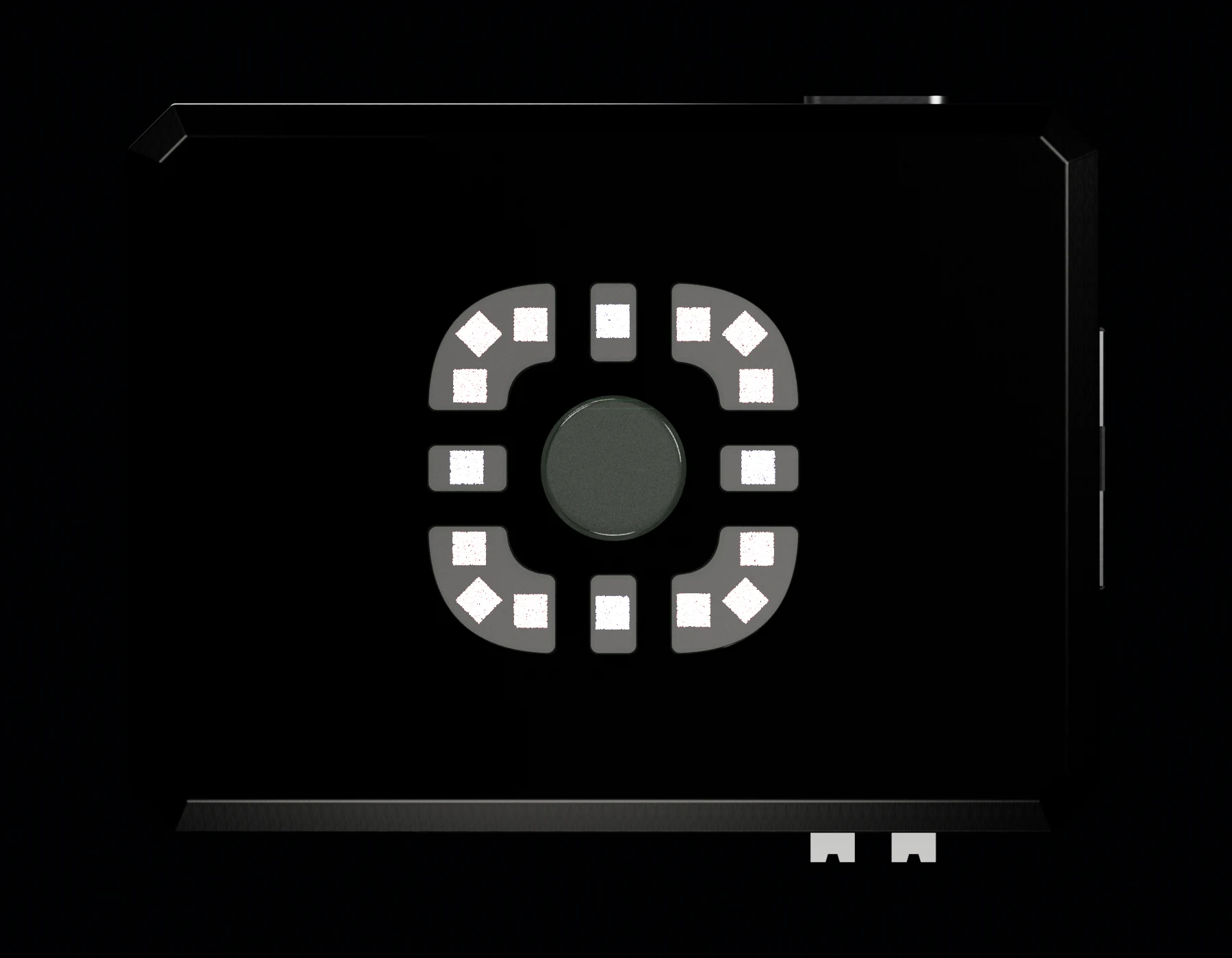
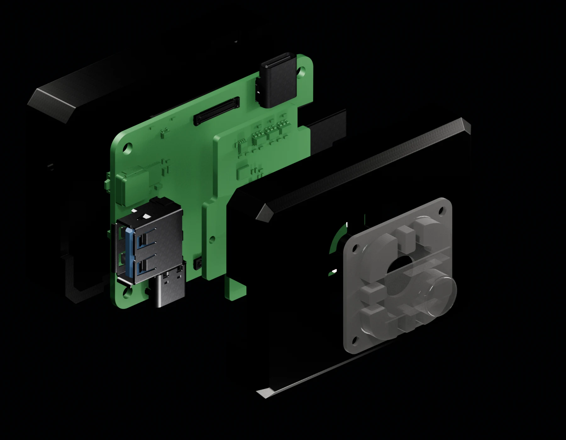
These views come from the authored assembly, not a generic product mockup. They show how the machined shell, front sensor geometry, internal board stack, and service access had to be resolved together.

Front orthographic CAD render of the authored Helios assembly
Front orthographicAuthored assembly / optical, illumination, and enclosure geometry
Exploded CAD render of the complete Helios assembly in physical stack order
Seven-part stackExploded on the true enclosure-depth axis
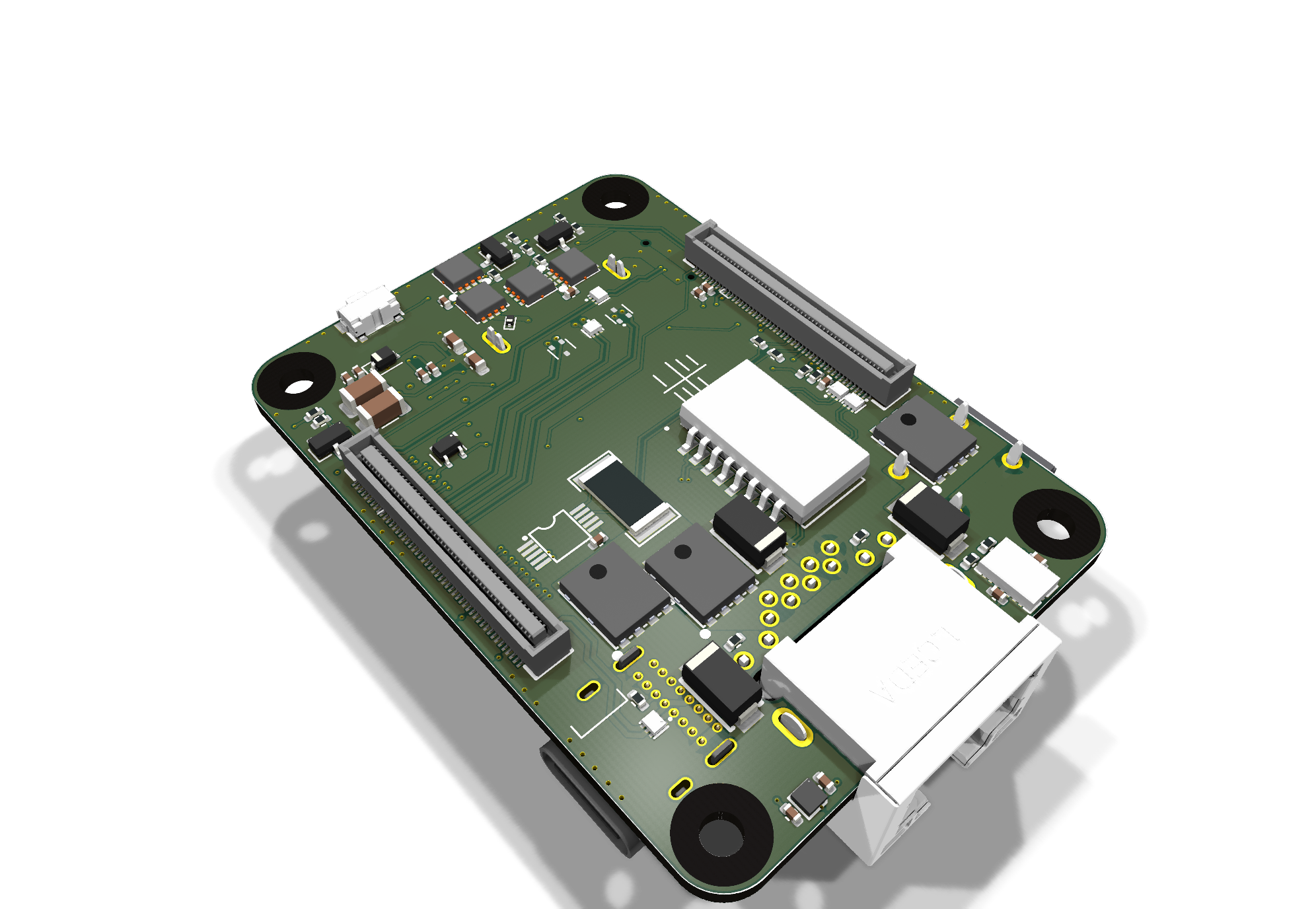
Isometric KiCad render of the Helios compute carrier
Board-level packagingConnector placement follows the enclosure and robot wiring paths
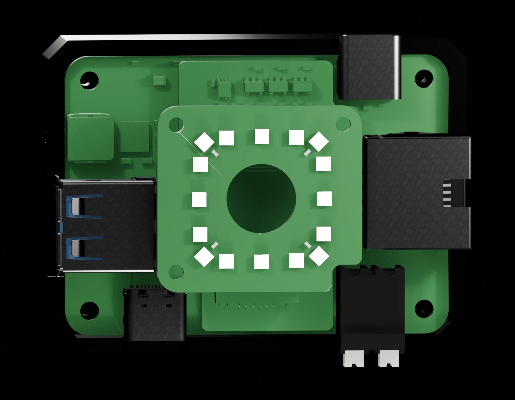
Shell-off CAD view of the Helios internal PCB and connector arrangement
Shell-off internal stackCarrier, camera interface, sensor ring, and edge connectors in assembled position
05 / Custom electronics

Both sides
of every board.

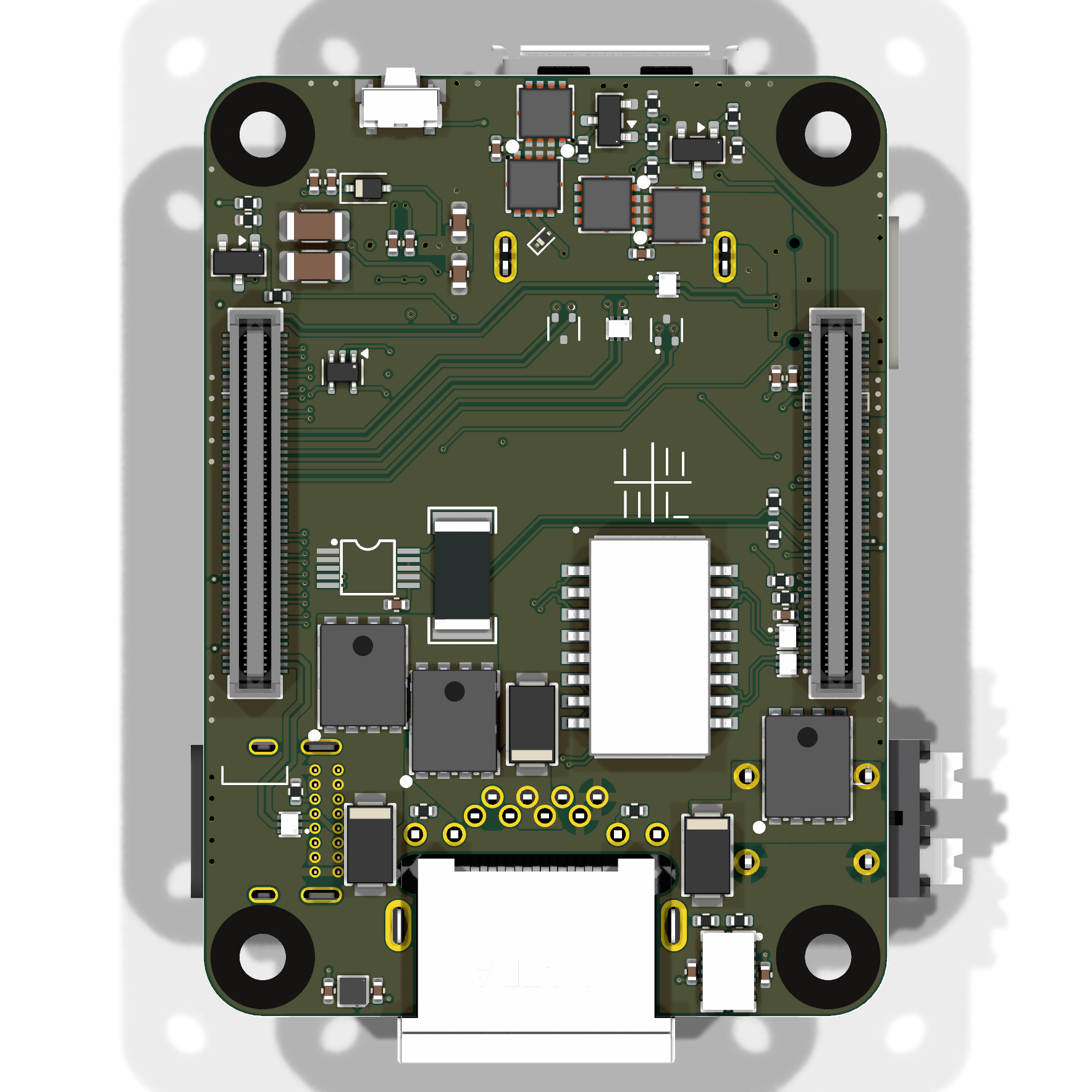
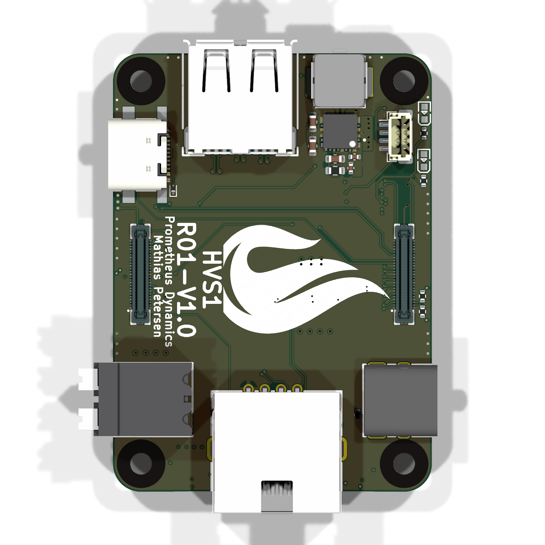
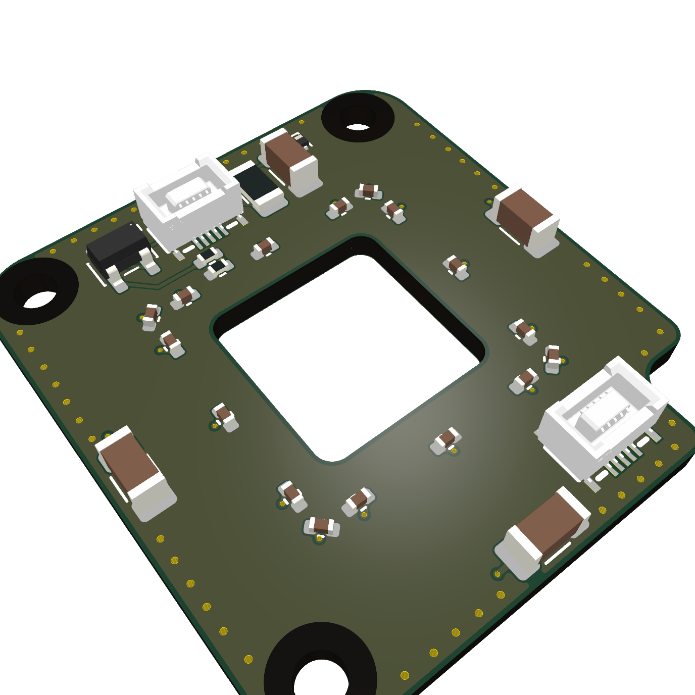
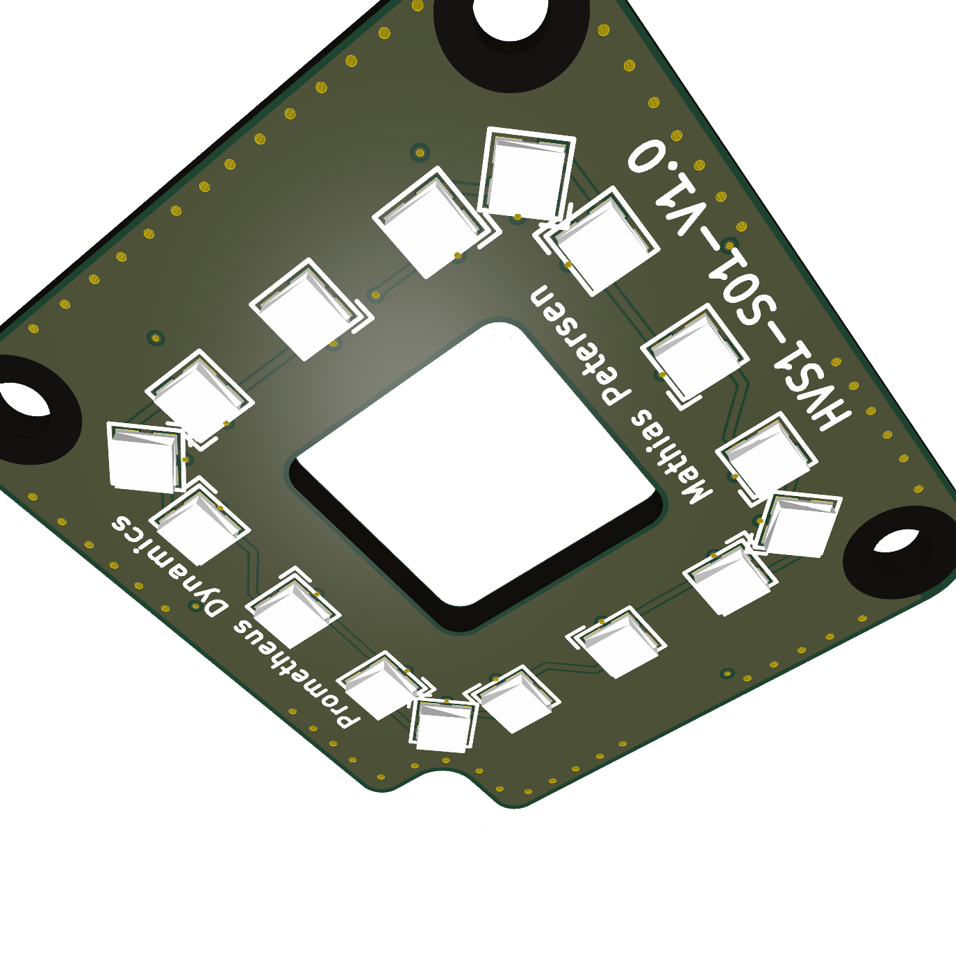
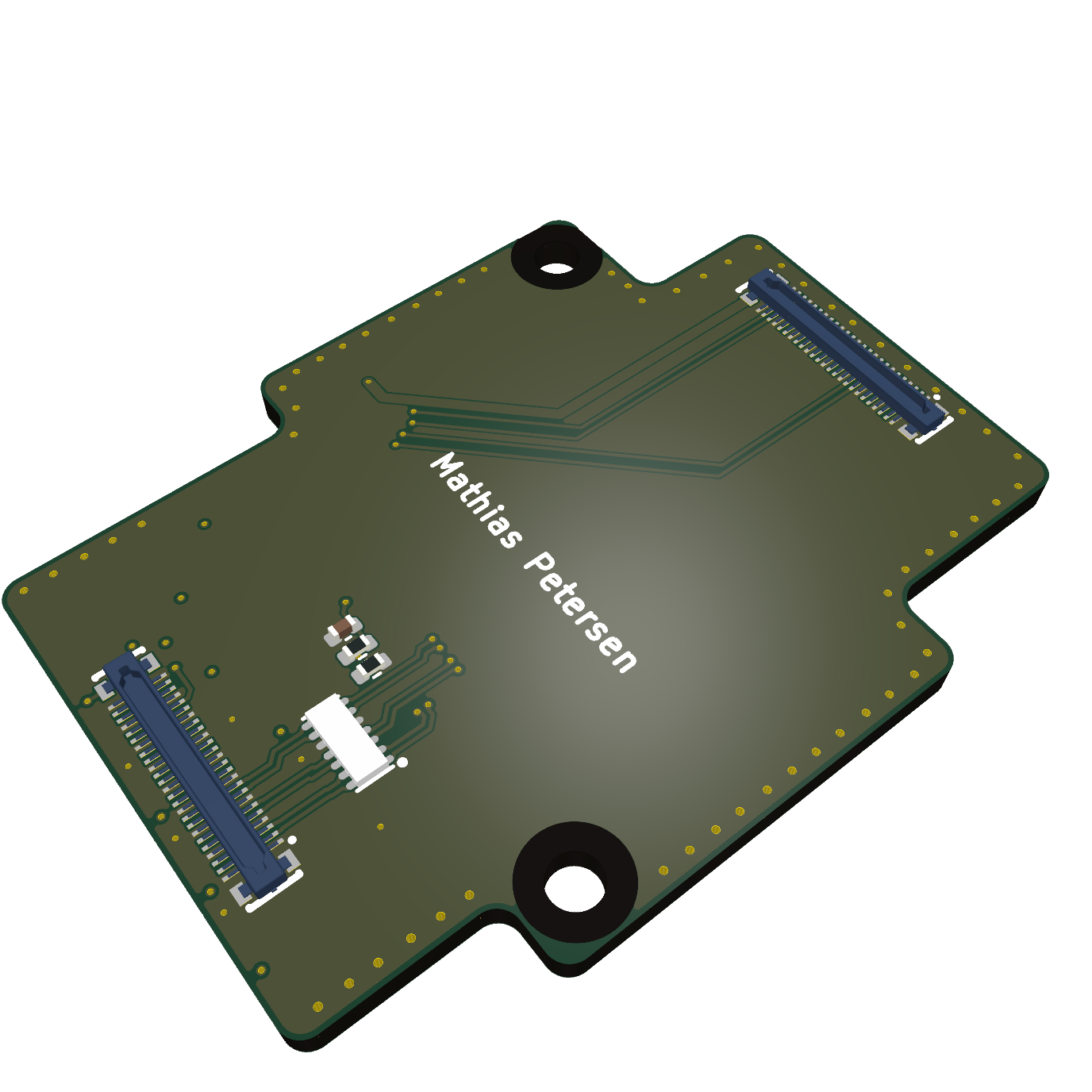
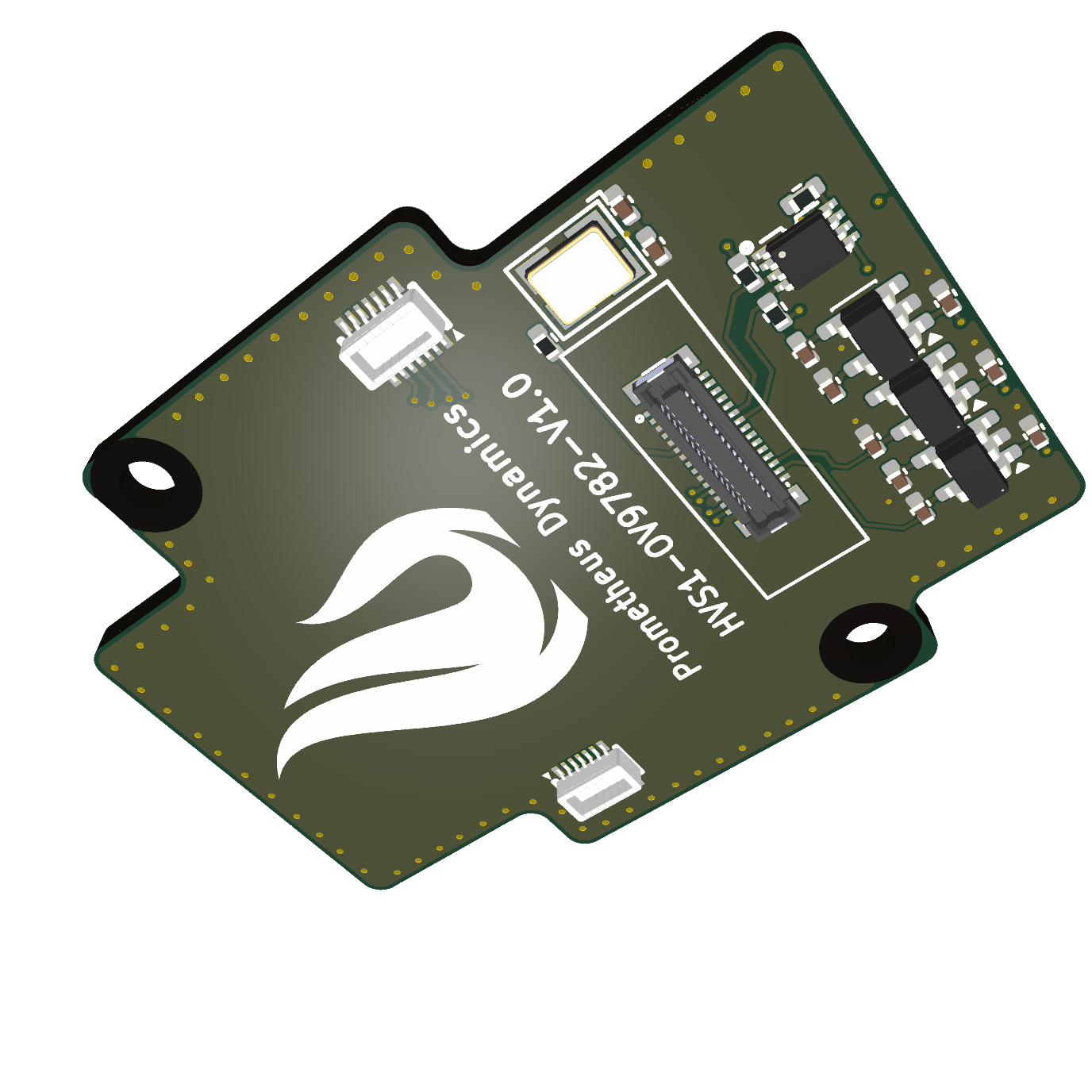
Direct KiCad renders show the component and reverse sides rather than treating each PCB as a single decorative image.

HVS-R01-V1.0

Compute carrier

Six copper layers · compute, power, cameras, networking, and external I/O.

Top side of the Helios compute carrier PCB
Component side / KiCad source
Bottom side of the Helios compute carrier PCB
Reverse side / KiCad source
HVS-S01-V1.0

Sensor ring

Top side of the Helios sensor-ring PCB
Front
Bottom side of the Helios sensor-ring PCB
Back
HVS-OV9782-V1.0

Camera board

Top side of the Helios camera-interface PCB
Front
Bottom side of the Helios camera-interface PCB
Back
06 / Architecture + validation

The decisions behind the product.

System architecture

  1. 01

    One product boundary power, compute, cameras, robot I/O, thermals, software, and recovery were designed together instead of sold as an accessory bundle

  2. 02

    Three purpose-built boards the compute carrier, sensor ring, and camera interface can follow different mechanical, routing, and revision constraints

  3. 03

    Local appliance the UI, API, processing, configuration, and recovery paths remain available on the robot network without a cloud dependency

  4. 04

    Field recovery by design A/B system slots, persistent data, USB networking, and diagnostics preserve a path back when an update or network configuration fails

Proof and field validation

  1. 01

    Manufacturing evidence a 50-device run exercised board test, enclosure fit, final assembly, image provisioning, and bring-up as one repeatable workflow

  2. 02

    Field evidence approximately 25 sold or sponsored systems moved the design from bench fixtures onto competition robots

  3. 03

    Revision evidence support cases were traced across hardware, software, documentation, and recovery paths, then fed back into the relevant product boundary

07 / Productization

Designed to leave the desk.

The work continued through enclosure iterations, thermal constraints, assembly, a 50-device production run, documentation, deployment, and direct support for teams using it on real robots.
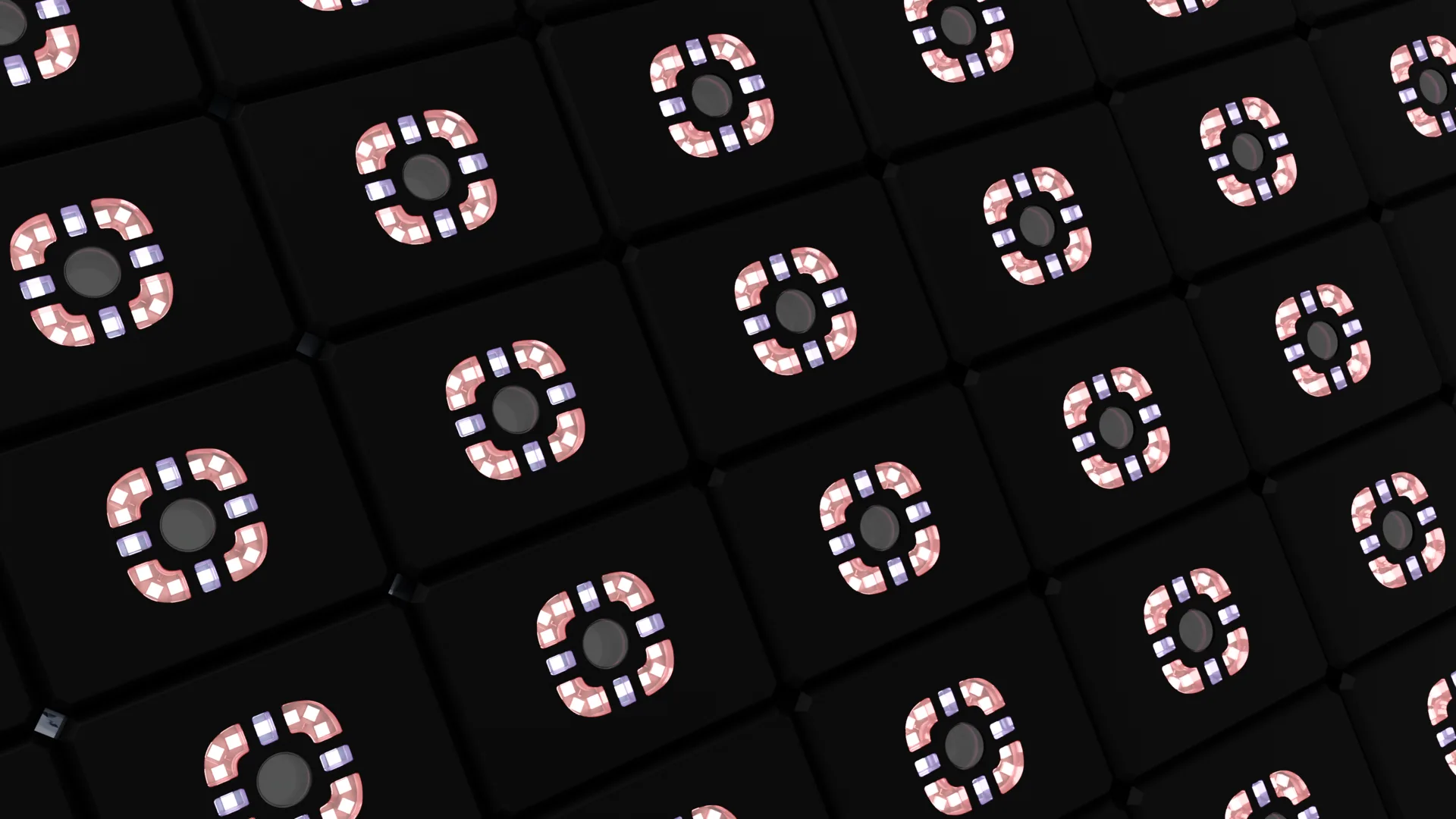
Production array of Helios cameras
08 / Embedded platform

The hardware has an operating layer.

Continue to HeliOS →
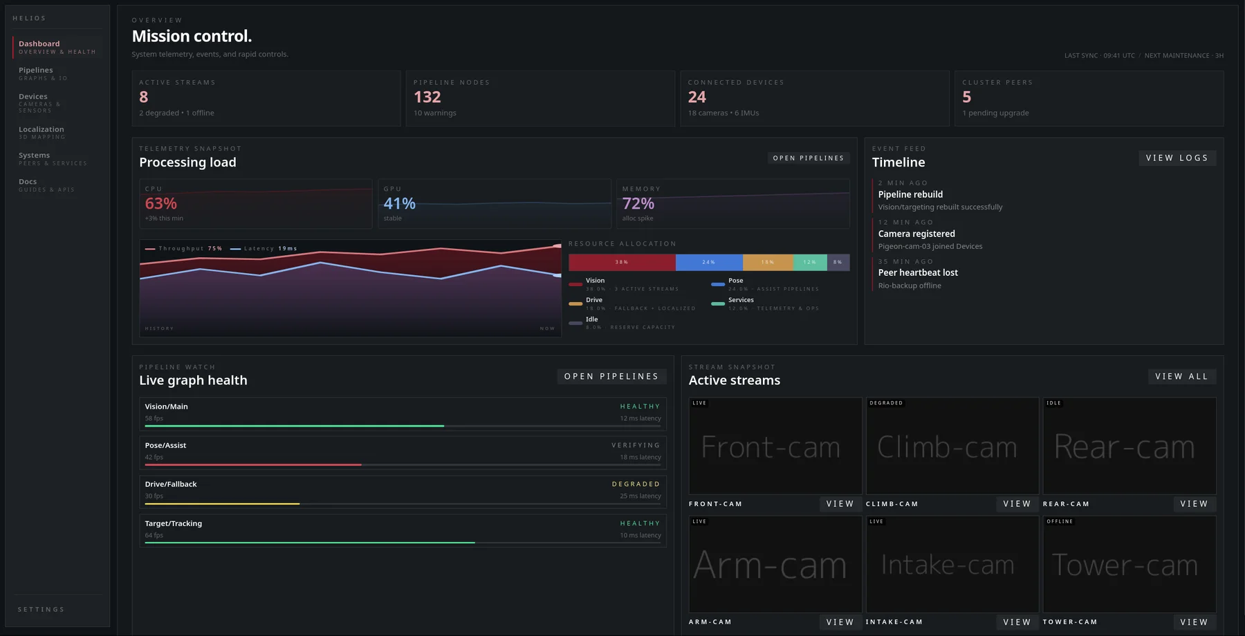
HeliOS mission control dashboard